Reverse-Engineering of a Bicycle Bell
July 2014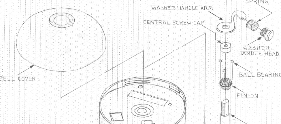
A project for the ‘Introduction to Engineering Design and Graphics’ course for mechanical engineers.
My first college engineering class ever, ‘Introduction to Engineering Design and Graphics’, was one of the most fun and engaging courses of my freshmen year. Throughout the semester, I learned about drafting conventions used by engineers, 3D computer-aided design modeling, rapid prototyping technologies, and basic manufacturing processes. The course was combined with a semester-long project in which teams reverse-engineered a simple mechanically driven machine, analyzed and drafted its components, and finally recreated all its parts using 3D modeling software and a 3D printer.
My group and I decided to work on a bicycle bell for this project, which had few parts and was completely driven by gears and springs. The initial stages of the project consisted of disassembling the bell into all its components and analyzing them to determine the purpose they served in the machine as well as determining the material of the parts and the most probable method used to produce them.
After we had been introduced to proper drafting conventions, the next stage of the project was to measure and draw each part to scale in isometric projection, by hand. The picture below shows select drawings our team submitted as part of our final report.
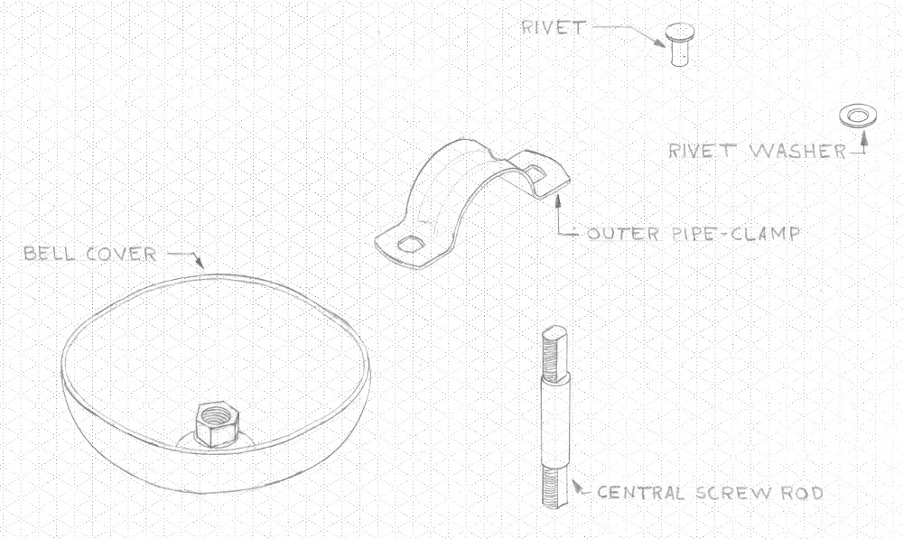
All of the parts shown above were drawn by me! :D
After each part had been individually drawn and labeled, the parts then needed to be redrawn on a single page to scale in an exploded view diagram showing each part’s location within the bell. A part of that drawing is shown at the header of this article.
Once these drawings had been finished, our team now needed to recreate each part using SolidWorks 3D modeling software according to the measurements that had been done earlier. After the part’s geometry and dimensions had been finalized within the software, 3-view drawings were made using SolidWorks, as shown below.
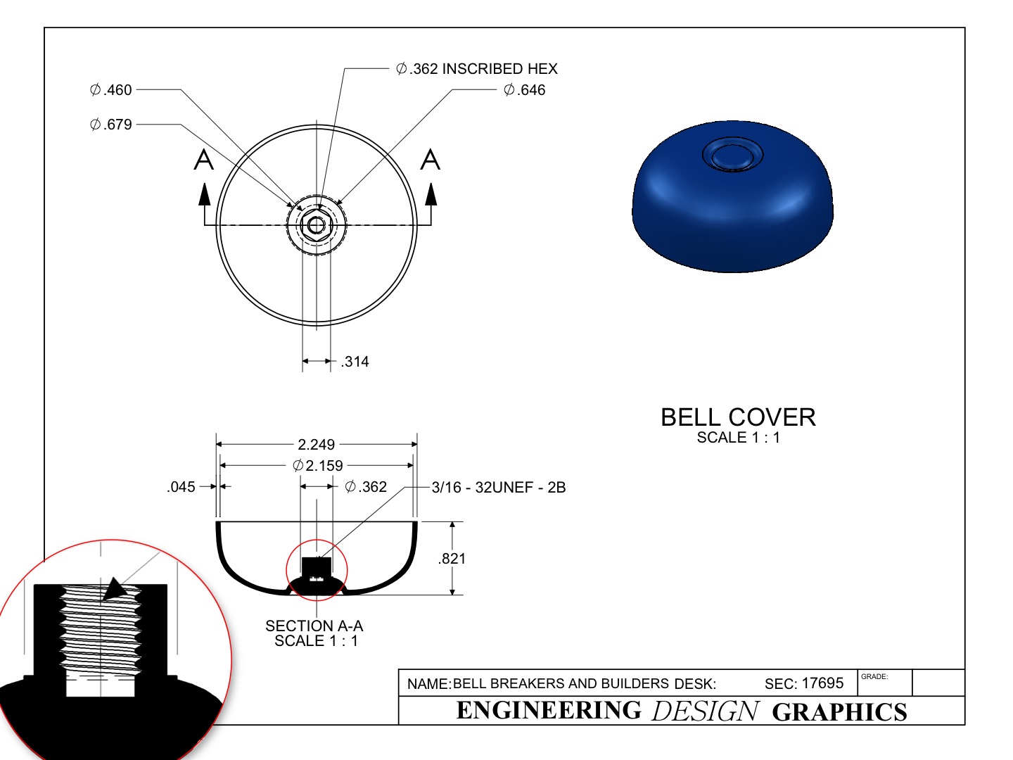
A 3-view drawing showing the dimensions and features of the bell cover.
With all the parts modeled in SolidWorks, it was only a matter of combining and linking all the files together to make a 3D rendering of the exploded view showing all the parts, similar to the one we had to sketch by hand.
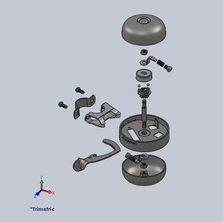
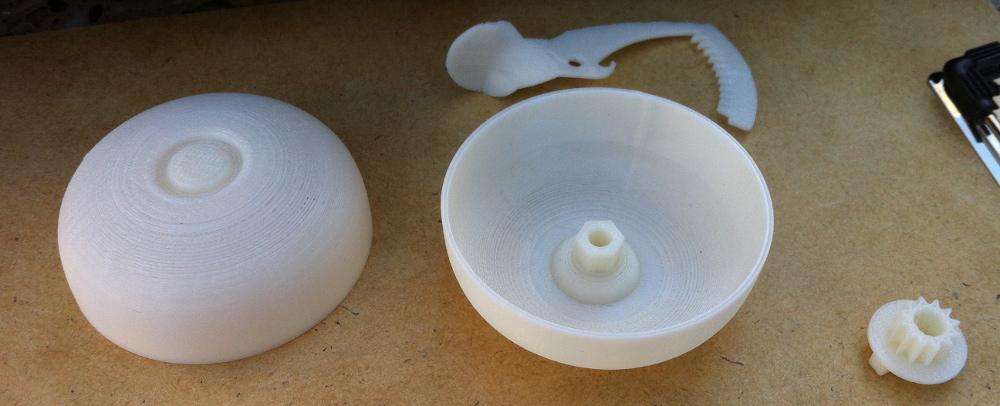
At the end of the semester, our project culminated with the 3D printing of our SolidWorks part models, through the use of the mechanical engineering department’s 3D printers. Overall, our parts matched up pretty well with the actual bell parts, with the exception of the threaded parts. Unfortunately, the small threads were below the resolution of the printer and thus made our bolts and threaded rod unable to join together like a regular screw.
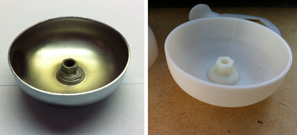
A comparison between the actual metal bell cover, and the plastic, 3D printed cover that I modeled using SolidWorks. All dimensions matched perfectly, with the exception of the threads as described above.
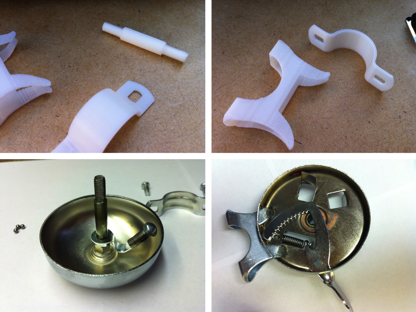
Comparison of select 3D printed parts with their original counterparts
My team and I were very satisfied with the outcome of the project, and I am very proud of all the work I put into it. This project allowed me to practice my drafting and 3D modeling skills on producing an actual product, and helped me gain many abilities I did not previously have, such as working with SolidWorks, 3D printers, and even operating milling machines and lathes from the department’s machine shop!
